
DMX & Arduino – need help to get started. :(
category: general [glöplog]
OK, this might be not exactly the right place to ask about this, but I noticed some here are experienced in electronics etc.
Our university has purchased one of these DMX to PWM converters from tinker.it:
http://www.tinker.it/en/Products/DMXInterface
The manual (linked on the site) has schemes of the wiring and some example code. We wanted to try the "heartbeat example", but have problems with the wiring... if you look at the scheme, at dmx-in, black must go to digital out (pin 3 in the heartbeat example code), blue to ground, but where does red lead to?
Also, we don't know wich adress has to be set by the switches for the example.
I am posting here because we are totally stuck. I have also posted at the official arduino forum (no response yet) and mailed to tinker.it, but we are a bit in a hurry.
So if you have any clue or experience in arduino with dmx, please help!
Thanks in advance!

to me it looks like black is ground - if you mean the figure under "Connections"

ok i read up a bit on DMX; wikipedia states:
The connectors themselves must be five-pin XLR, although only three pins of the five are always used.
The pin layout from DMX512-A is :
1. Data Link Common
2. Data 1- (Primary Data Link)
3. Data 1+ (Primary Data Link)
4. Data 2- (Secondary Data Link)
5. Data 2+ (Secondary Data Link)
so 1 would be blue, 2 would be red and 3 would be black, i assume.
DMX is using a balanced line (read this, it's important), so the black wire is ground and the red and blue wires are the positive and negative parts of the signal.

...and while this isnt necessarily relevant to your problem the heartbeat example actually credits someone who i assume is rod/mandula :D
no,
1 - black
2 - blue
3 - red
1 - black
2 - blue
3 - red
(in other news, the German wikipedia page on DMX is way better than the english one. :)
thanks!
but does anybody can see from the code what the missing pin could be? one of blue and red goes to pin 3, but the other one?
And about the adress... we tried a few, but there are 509 possibilities...
but does anybody can see from the code what the missing pin could be? one of blue and red goes to pin 3, but the other one?
And about the adress... we tried a few, but there are 509 possibilities...
Oh, and red leads to pin 3 (hot), right?
what kind of connector are you using anyway? :o
Maw, as said, it's using a balanced line. if you only got one output pin and ground, try connecting that to the "D+" (out) and "D-" (ground) ports of the PWM interface and ignore the "-" port completely. If that doesn't help you'll need a signal balancer of some kind.
And judging from the source code it doesn't matter what channel you set the interface to, that program outputs the heartbeat signal on all DMX channels at once.
And judging from the source code it doesn't matter what channel you set the interface to, that program outputs the heartbeat signal on all DMX channels at once.
@ gargaj: if you mean the connection from the arduino board to the converter, we use plain wires...
@ kb_: thanx, I'll give it a try later!
@ kb_: thanx, I'll give it a try later!
so, I tried, but it still doesn't work... maybe it's because of the adress (not the channel) wich has to be set by the jumpers?
Here's a pic of the whole thing:
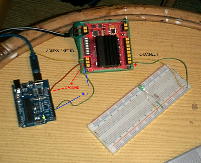
(sry for the quality, cheap digicam)
Here's a pic of the whole thing:
(sry for the quality, cheap digicam)
maw: you need to connect the ground cable to D- and pin 3 to D+. Also, a) have you set a DMX channel with the switches? b) does the self test mode (address 0, should flash with all LEDs) work?
And on a more serious note: Since when has it become so out of fashion to READ stuff at a fucking UNIVERSITY? I gathered all knowledge I presented here from the manual, the source code and a few Wikipedia articles, so what's your excuse?
Common problem, I guess.

@ kb_: I also tried to connect it the other way around, still didn't work. The self test mode works a bit, since the LEDs are not flashing but permanently on. I have set an adress with the switches, not a channel. All the channels get output from the programm.
OK, and about reading stuff... I _did_ read the artikel about balanced line. I also read the article about dmx. And of course the source. The problem is that I am really not into electronics and such. I am studying graphic design and chose this "physical computing" lectures as an experiment.
I am sorry if I seem stupid or lazy. I think I am not. It's just that circuits, assembling electronic components etc. is not my field! I try, but find it really hard to understand even the very basics of all this stuff. So I ask.